



A taper is quickly drawn, but on the lathe you need to know how many degrees to swivel the compound slide. Here you can see how to work out the taper ratio and the setting angle from the dimensions on the drawing, and when the tailstock is a better choice than the compound slide.
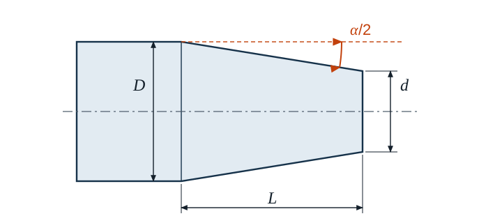
Taper ratio
The taper ratio tells you by how many millimetres the diameter decreases over a certain length. On drawings it is usually given as a ratio, for example 1 : 10 – the diameter gets 1 mm smaller over a length of 10 mm.
- C taper ratio (as a number or as 1 : x)
- D large diameter in mm, d small diameter in mm
- L taper length in mm
Setting angle for the compound slide
The compound slide is swivelled by half the taper angle α/2. You get it via the tangent. Because the diameter decreases on both sides of the axis, half the difference in diameter goes in the numerator:
Example
A taper is to be turned using the compound slide (D = 30 mm; d = 24 mm; L = 60 mm).
C = 30 mm − 24 mm60 mm = 0.1 = 1 : 10
tan α2 = 0.12 = 0.05 → α2 ≈ 2.8624° ≈ 2° 51′ 45″
The compound slide is swivelled by just under 2° 52′. Radially, you need to feed in a total of (30 − 24) / 2 = 3 mm.
Degrees, minutes, seconds
Many scales on the compound slide are divided into degrees and minutes. The calculator gives decimal degrees. To convert, multiply the decimal part by 60. So 0.8624° · 60 = 51.74′ gives 51 minutes, and 0.74′ · 60 gives about 45 seconds. So 2.86° is not 2° 86′ but 2° 51′ 45″.
Compound slide or tailstock?
The compound slide can set any angle, but its travel is short and it is moved by hand. For long, slender tapers you can instead offset the tailstock sideways and turn the workpiece between centres with longitudinal feed. The offset then depends on the total workpiece length LW:
This is only suitable for slender tapers. If the offset becomes larger than about one fiftieth of the workpiece length, the centres sit askew in the centre holes. That is the case for all tapers steeper than 1 : 25 – so for the 1 : 10 example above, the compound slide is the better choice.
Morse tapers and steep tapers
Tool holders are standardised tapers. Morse tapers are very slender and, depending on size, are close to 1 : 20, but not exactly – MT 3, for example, is about 1 : 19.922. Steep tapers for milling tool holders are 7 : 24 and are not self-holding; they are drawn in.
Common mistakes
- Swivelled by α instead of half the angle: the taper becomes twice as steep.
- Diameter difference not halved: in the tangent, (D − d) / 2 goes over L, not D − d.
- 1 : 10 entered as ten: as a number, C = 0.1.
- Taper length instead of workpiece length for the tailstock: the offset refers to the entire length between centres.
- Calculator not set to degrees: arctan then returns a value in radians.
- Decimal degrees read as minutes: 2.86° becomes 2° 51′ 45″, not 2° 86′.