



The drawing says Ø 40 H7/g6 – and you need to know what size the hole may be, what size the shaft may be and whether the two will later slide into each other easily or only go together with a press. Here you learn how to read a fit designation like this and work it out step by step.
What the fit designation tells you
A fit always describes two parts that belong together: an internal part (shaft) and an external part (hole). Both have the same nominal size, here 40 mm. After it come two tolerance classes, first the one for the hole, then the one for the shaft.
- Capital letter = hole, lower-case letter = shaft. So H7 belongs to the hole and g6 to the shaft.
- The letter defines where the tolerance zone lies: directly on the zero line (H, h), below it or above it. The technical term is fundamental deviation.
- The number is the standard tolerance grade (IT). The smaller the number, the narrower the tolerance zone and the more accurately the part has to be made.
In mechanical engineering the hole-basis system (basic hole) is the usual choice: the hole gets H (lower deviation 0), and the required fit is achieved through the shaft alone. That saves reamers and plug gauges, because shafts are easier to bring to any size on the lathe. With the shaft-basis system (basic shaft) it is the other way round: the shaft gets h (upper deviation 0), for example with drawn bright steel that is fitted without machining.
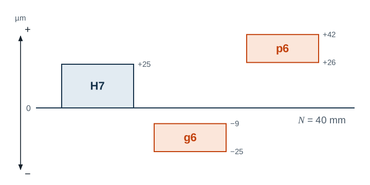
The formulas
Each part has an upper and a lower deviation. For the hole they are called ES and EI, for the shaft es and ei. They give you the limits of size:
For the shaft, use es and ei. Comparing the two parts tells you whether you get clearance or interference:
- N nominal size
- Go, Gu maximum and minimum limit of size
- ES, EI upper and lower deviation of the hole
- es, ei upper and lower deviation of the shaft
- Smax, Smin maximum and minimum clearance; a negative value is interference
Example with Ø 40 H7/g6
Example
We need the limits of size of the hole and the shaft and the type of fit. The deviations for the nominal size range over 30 up to 50 mm are:
| upper deviation | lower deviation | maximum size | minimum size | |
|---|---|---|---|---|
| Hole H7 | +25 µm | 0 µm | 40.025 mm | 40.000 mm |
| Shaft g6 | −9 µm | −25 µm | 39.991 mm | 39.975 mm |
The maximum clearance occurs with the largest hole and the smallest shaft:
Smax = 25 µm − (−25 µm) = 50 µm
The minimum clearance occurs with the smallest hole and the largest shaft:
Smin = 0 µm − (−9 µm) = 9 µm
Both values are positive, so it is a clearance fit. The shaft always turns easily, but without any noticeable wobble.
Counter-example with Ø 25 H7/p6
Here the tolerance zone of the shaft lies above that of the hole. The hole measures 25.000 to 25.021 mm, the shaft 25.022 to 25.035 mm.
Smax = 21 µm − 22 µm = −1 µm Smin = 0 µm − 35 µm = −35 µm
Both values are negative: an interference fit with 1 to 35 µm interference. The parts are pressed in or assembled by heating the hole.
Clearance, transition or interference?
| Result | Type of fit | Typical application |
|---|---|---|
| Minimum clearance ≥ 0 | Clearance fit | Plain bearings, guides, spigots that are taken apart |
| Maximum clearance ≤ 0 | Interference fit | Bushes, gears and hubs without a key |
| in between | Transition fit | Parts that locate precisely and can be assembled with light taps |
Some pairings come up particularly often. H7/h6 lets parts be slid by hand, H7/g6 gives easy running fits, H7/k6 is a transition fit for gears and pulleys with a key, and H7/p6 stands for press fits.
Common mistakes
- Sign when subtracting: minus times minus gives plus. 25 − (−25) is 50, not 0.
- Hole and shaft swapped: if you assign H7 to the shaft, you get a completely different result. A capital letter means hole.
- Wrong nominal size range: the ranges apply “over … up to and including”. 30 mm still belongs to the range over 18 up to 30.
- Negative clearance not recognised: a clearance of −35 µm is an interference of 35 µm, not a calculation error.
- Made to the nominal size: with H7, 40.000 mm is just about acceptable, but right at the limit. If you aim for the middle of the tolerance (here 40.0125 mm), you have a margin on both sides.
Frequently asked questions
Why are the tolerance zones wider for larger diameters?
Manufacturing and measuring errors grow with the diameter. The standard therefore divides nominal sizes into ranges, and each range has a slightly larger tolerance for the same grade. For IT7, for example, it is 21 µm up to 30 mm and 25 µm up to 50 mm.
Do I have to know the deviations by heart?
No. What matters is that you can read the designation and reliably work out the limits of size. You look up the deviations or let them be calculated for you.