




On a conventional lathe you cannot set the spindle speed freely. You shift levers according to the plate on the headstock, and the machine only offers fixed steps. Your calculation says 1273 1/min, the plate shows 1000 and 1400. Which step is right? Here you learn why the steps are spaced the way they are, how much cutting speed you lose by shifting down and when the higher step is the better choice.
Why the gaps get bigger towards the top
Look at a typical speed plate, for example with twelve steps from 45 to 2000 1/min. At the bottom the steps are only 18 1/min apart, at the top 600 1/min. That is no coincidence. Each step is larger than the previous one by the same factor. This factor is called the step ratio.
- φ step ratio
- nk one speed step, nk+1 the next higher one in 1/min
- nmax, nmin highest and lowest step in 1/min
- z number of steps
For the plate with 45 to 2000 1/min and twelve steps there are eleven jumps.
φ11 = 200045 ≈ 44.4 φ ≈ 1.41
The values come from a preferred number series, which is why they are rounded. From 45 to 63 the factor is 1.40, from 90 to 125 about 1.39 and from 125 to 180 exactly 1.44. On average it is 1.41.
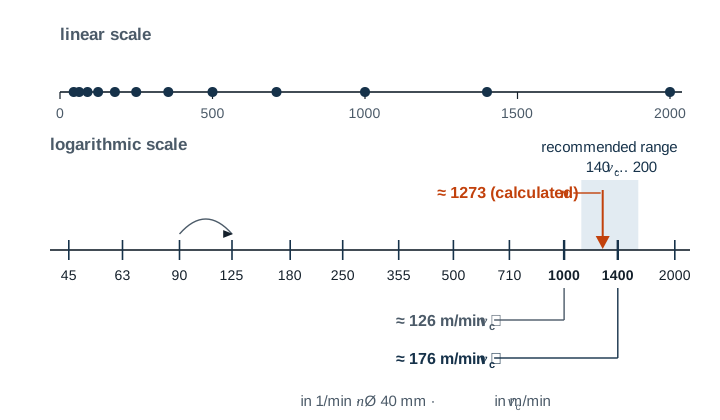
The advantage of this series is that you lose the same percentage at every step. Whether your calculation says 1390 1/min and you shift to 1000, or it says 174 1/min and you shift to 125, about 28 % is missing in both cases. The worst case is the same everywhere.
| Step ratio φ | Largest loss of vc with the next lower step |
|---|---|
| 1,12 | 11 % |
| 1,25 | 20 % |
| 1,41 | 29 % |
| 1,58 | 37 % |
Older or small machines often have few steps with a large step ratio. There it is especially worth calculating both neighbouring steps.
The basic rule and its exception
The basic rule is the next lower step. The tool life of the cutting edge depends strongly on the cutting speed, and even a little too much costs a lot of tool life. A cutting speed that is slightly too low is usually harmless.
Guide values for the cutting speed, however, come as a range, not as a single number. If the lower step falls below this range, carbide cuts worse. With steel the surface gets rougher, and at a very low cutting speed a built-up edge forms. Then the next higher step is right, as long as it stays within the range. This is how you proceed.
- Determine the calculated spindle speed from the planned cutting speed.
- Work out the actual cutting speed for the two neighbouring steps.
- If the lower step is within the guide value range, take it. Otherwise take the higher one if it is within the range.
- vc actual cutting speed in m/min
- d diameter at which the cutting edge is currently cutting, in mm
- n selected speed step in 1/min
A useful relationship here is that the two neighbouring steps differ by exactly the step ratio. If the guide value range is at least as wide as the step ratio, meaning the upper end is at least 1.41 times the lower end, and the spindle speed lies within the plate, then one of the two steps almost always fits. Because the step values are rounded, it is better to leave some margin.
Example 1 – the higher step is right
A shaft made of C45 with Ø 40 mm is longitudinally turned with a carbide indexable insert. The guide value range is 140 to 200 m/min, the plan is 160 m/min.
n = 160 · 1000π · 40 ≈ 1273 1/min
Step 1000 → vc = π · 40 · 10001000 ≈ 126 m/min
Step 1400 → vc = π · 40 · 14001000 ≈ 176 m/min
With 1000 1/min a good 20 % is missing, and you are below the range. With 1400 1/min you are just under 10 % above the planned value, but still within the range. Here 1400 1/min is the better step.
Example 2 – the lower step is right
A pin made of S235 with Ø 50 mm is turned with an HSS turning tool. The guide value range is 25 to 35 m/min, the plan is 30 m/min.
n = 30 · 1000π · 50 ≈ 191 1/min
Step 180 → vc ≈ 28 m/min Step 250 → vc ≈ 39 m/min
Step 180 is within the range and just below the planned value. With 250 1/min you would be above the range, which is too fast for HSS. You take 180 1/min.
The values in the example are guide values. The tool manufacturer's data take precedence.
When the machine reaches its limits
With very large and very small diameters the plate is sometimes not enough.
- Calculated speed below the lowest step: A disc with Ø 300 mm is to be rough-turned with HSS at 20 m/min. That works out to about 21 1/min, but the machine can only do 45 1/min. The cutting speed then rises to about 42 m/min, twice as much. A carbide indexable insert helps here. 42 m/min is below its range, but it does not overload it. If you stay with HSS, you must clearly reduce the depth of cut and the feed.
- Calculated speed above the highest step: A pin made of aluminium with Ø 10 mm would need about 9549 1/min with carbide at 300 m/min. With the highest step of 2000 1/min you only reach about 63 m/min. That does not harm the cutting edge, but it takes longer, and the surface can get worse.
Common mistakes
- Shifted with the spindle running: This damages the gears in the headstock. Only shift at standstill, unless the operating manual allows otherwise.
- Calculated with the finished size: When roughing, the insert cuts on the blank. If the shaft from example 1 is pre-turned from Ø 50 mm, step 1400 gives about 220 m/min there and is above the range.
- Always chose the higher step: That saves a few seconds and costs a lot of tool life. Calculate first, then shift.
- Overlooked the maximum speed of the clamping device: Every chuck and every faceplate has a permissible maximum speed. Long bars that stick out of the back of the spindle must be supported.
- Misread the lever positions: Many machines have two or three levers. Only when all of them are set as shown on the plate is the speed correct.
Frequently asked questions
Why not simply equal gaps, for example every 180 1/min?
Then the first steps would be 180 and 360 1/min. For a large diameter with 100 1/min you would have no suitable step, the jump at the bottom would be huge. At the top, on the other hand, 1800 and 1980 1/min would hardly differ. With the same factor every step is the same size in proportion, and that is exactly what matters for the cutting edge.
Where do I find this in the app?
In Gesello, in the Cutting data module, under Turning in Machine steps. You enter the steps of your lathe once. After that the app shows you the next lower step for the calculated spindle speed and the cutting speed you actually reach with it. You find the formulas in the calculation guide Calculating spindle speed and feed rate.