



The bore has been reamed, and the drawing says Ø 20 H7. Now a limit plug gauge, an inside micrometer and a bore gauge with dial indicator are lying on the workbench. All three check bores, but not all of them are accurate enough for H7, and two of them measure at only two points. They can easily miss an out-of-round bore. Here you find out which instrument suits which job.
How tight H7 really is
For a hole, H7 always means a lower deviation of zero. So the minimum size is the nominal size, and upwards the standard tolerance grade IT7 is available. With Ø 20 H7 the bore may lie between 20.000 mm and 20.021 mm. How to determine the limits of size for any fit is shown in the calculation guide Calculating ISO fits. This article is about how you prove that the bore is within tolerance.
The golden rule of metrology
21 µm is less than the thickness of a hair. The measuring instrument should resolve at least ten times finer than the width of the tolerance. Strictly speaking, the measurement uncertainty is what counts; as a first guide, use the digit step or the scale interval.
- V ratio of tolerance to resolution
- T tolerance of the bore in µm
- u resolution or measurement uncertainty of the instrument in µm
From V = 10 the instrument is suitable, between 5 and 10 only conditionally, below 5 not at all. These are guide values; requirements from the inspection plan and the drawing take priority. For Ø 20 H7 this gives the following overview.
| Measuring instrument | Resolution in µm | V at 21 µm | Rating |
|---|---|---|---|
| Inside micrometer with measuring jaws | 10 | 2,1 | not suitable |
| Bore gauge with dial indicator | 10 | 2,1 | not suitable |
| Three-point inside micrometer with 5 µm scale interval | 5 | 4,2 | not suitable |
| Three-point inside micrometer with 1 µm digit step | 1 | 21 | suitable |
| Bore gauge with dial comparator | 1 | 21 | suitable |
| Limit plug gauge 20 H7 | – | – | suitable, but without a measured value |
With larger bores, H7 gets wider. Ø 80 H7 already has 30 µm of tolerance, so the three-point inside micrometer with 5 µm reaches V = 6 and is conditionally usable. Up to 30 mm diameter you need a resolution of 1 µm for H7; from 18 mm, 2 µm is also enough. Or you use the gauge.
Limit plug gauge – fast and unambiguous
The limit plug gauge has two test cylinders. The GO side has the minimum size, here 20.000 mm, and must slide into the bore without force. The NO-GO side has the maximum size, here 20.021 mm. It is shorter, marked red, and may at most just catch, but must not enter.
- Strength: the GO side is a long cylinder. It behaves like the shaft that will go in later and also detects form errors that make the bore narrower, for example out-of-roundness or taper.
- Weakness: you get no measured value. Whether the bore is at 20.002 mm or at 20.019 mm, the gauge does not tell you. You only notice a wearing reamer when the GO side no longer goes in.
For series production, the plug gauge is the first choice. If you want to adjust the size, you need a measuring instrument with a display.
Two points or three points?
The inside micrometer with measuring jaws and the bore gauge touch the bore at two opposite points. The three-point inside micrometer has three measuring anvils 120° apart and centres itself. This decides which form errors you can see.
A typical case is a thin-walled ring that is clamped in a three-jaw chuck and bored. The jaws press it in slightly at three places. After unclamping it springs back, and the bore has three flat lobes instead of a circle. Such a shape is called a constant width form (lobed shape), because it is equally wide everywhere between two opposite points.
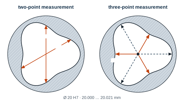
Example
After unclamping, a ring with Ø 20 H7 has a constant-width form. The smallest and the largest distance from the centre differ by 12 µm; that is the roundness deviation.
With two-point measurement you measure 20.010 mm all the way round, almost exactly the middle of the tolerance.
The three-point inside micrometer shows values between 19.998 mm and 20.022 mm in different angular positions. The range is twice as large as the roundness deviation.
20.022 mm − 19.998 mm = 0.024 mm = 2 · 12 µm
The three-point values are not diameters; they make the form error visible. What matters is the smallest value. A circle of 19.998 mm is the largest that fits into this bore, and it is below the minimum size. The limit plug gauge confirms this: its GO side with 20.000 mm does not go in. A shaft with 20.000 mm would therefore jam, even though the two-point measurement said “good”.
Conversely, two-point measurement clearly shows an oval bore if you measure again offset by 90°. Three-point measurement practically does not show a pure oval. So measure fit bores in several directions and at several depths, and if in doubt, combine both methods.
Bore gauge with dial indicator
The bore gauge only compares. You set it to zero in the setting ring and rock it in the bore. At the reversal point of the pointer you read the deviation from the setting size. With a dial comparator it is suitable for H7 and reaches far into deep bores. With a 0.01 mm dial indicator it is too coarse for small H7 bores.
Which instrument when?
| Situation | Good choice |
|---|---|
| Series production, many identical bores | Limit plug gauge, plus random checks with a measured value |
| Single part, size is to be adjusted | Three-point inside micrometer with 1 µm |
| Thin-walled parts clamped in a three-jaw chuck | Three-point measurement and limit plug gauge |
| Parts clamped in a vice, suspected oval | Two-point measurement in two directions |
| Deep or large bores | Bore gauge with dial comparator |
Common mistakes
- Measured warm: an aluminium housing comes out of the machine at 35 °C. With Ø 20 mm the bore is then about 7 µm larger than at 20 °C, a third of the tolerance. Let it cool down first, then check.
- Plug gauge pushed in: with force, the GO side often goes into a bore that is too small. The result is wrong, and the gauge wears.
- Measured at one point only: a measured value at the front of the bore says nothing about the middle. A bore can be bell-mouthed or barrel-shaped.
- Instrument not set: check three-point measuring heads and bore gauges in the setting ring before every measurement series.
Frequently asked questions
Why is the NO-GO side shorter?
The GO side checks the bore as a whole, just as the shaft will fit in later. The NO-GO side, on the other hand, is meant to check individual spots that could be too large. Ideally this would be contact at only two points. A short cylinder comes closer to that than a long one, and you can tell the sides apart at once.
Where can I find the measuring instruments and how to use them in the app?
In Gesello, in the Measuring and inspection module. There you find the instruments with a drawing, correct use and typical mistakes. You check whether a measuring instrument suits the tolerance and see which form errors two-point and three-point measurement detect.