




Can you read the correct view from a 3D drawing? It is part of every technical drawing and comes up in almost every exam. Here you will find three tasks from easy to hard, and you can expand the solution for each one. But first, the essentials of view layout in one minute.
How the views are arranged
In Europe, first-angle projection is usually used. Each view is placed opposite the direction you are looking from: the view from above goes below the front view, the view from the left goes to the right of it.
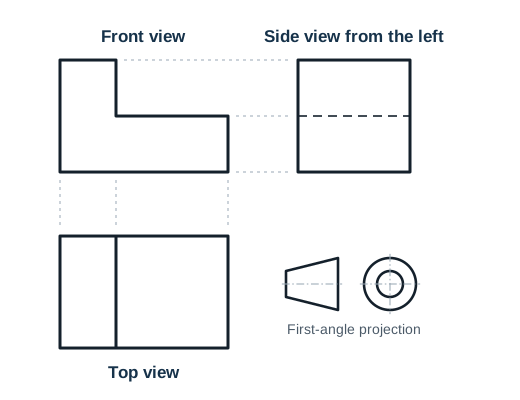
The symbol in the title block shows which method applies: truncated cone on the left, circles on the right means first-angle projection. It also appears at the top left of every exercise image.
- Visible edges are drawn as a wide continuous line.
- Hidden edges are drawn as a narrow dashed line.
- The arrow V shows the viewing direction of the front view.
- Areas you cannot see in the 3D drawing are solid.
Task 1: easy
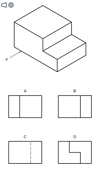
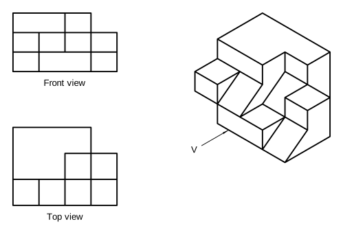
Which image shows the top view?
Show solution
The correct answer is image B. The top view is the view from above and is placed below the front view. Image A is mirror-inverted, image C shows the bottom view, i.e. the view from below, and image D belongs to a body with one cube missing.
Task 2: medium
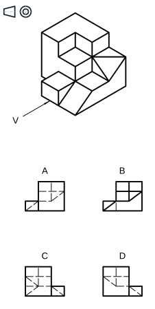
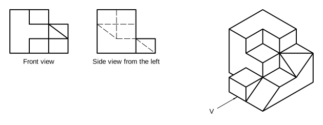
Which image shows the side view from the left?
Show solution
The correct answer is image D. The side view from the left is placed to the right of the front view. Watch the dashed lines: these edges lie behind the body. Image A is mirror-inverted, image B shows the side view from the right, and image C belongs to a body with an additional slope.
Task 3: hard
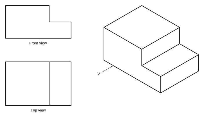
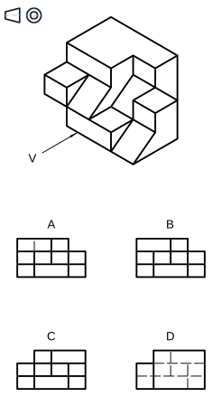
Which image shows the front view?
Show solution
The correct answer is image B. The front view is the view in the direction of arrow V. Image A belongs to a body with one cube missing, image C is mirror-inverted, and image D shows the rear view, i.e. the view from behind.
Common mistakes
- Read mirror-inverted: The image is right but flipped. Check on which side the high and the low parts are.
- Top view and bottom view mixed up: From below you see different edges than from above. Steps on top appear as dashed lines from below.
- Hidden edges forgotten: Edges behind the body also belong in the view, as a narrow dashed line.
- Left and right mixed up: In first-angle projection, the side view from the left is placed to the right of the front view.
More in Gesello
In the free module Reading drawings, the Views section explains first- and third-angle projection, the layout of the views and the symbol in the title block. In the Spatial visualisation module you find the views of 150 numbered practice solids, and in the Practice module you train with exam questions and explanations. And every two weeks there is a new 3D drawing quiz on Instagram, Facebook and TikTok.
Drawing symbols
FreeRead lines, edges and symbols correctly.
What does the chain line mean, and the edge symbol with a plus? Every symbol is cleanly drawn and explained, with an example and the most common mistake.
- Six groups
Lines, dimensions, surface, edges, threads, representation. - Detail sheet
Large symbol, meaning and example. - Common mistake
What often goes wrong in practice.
Also in the module
- SearchFinds symbols by character or word, such as Ø, chamfer or dashed line.
- Related modulesGo to form and position, threads or roughness with one tap.
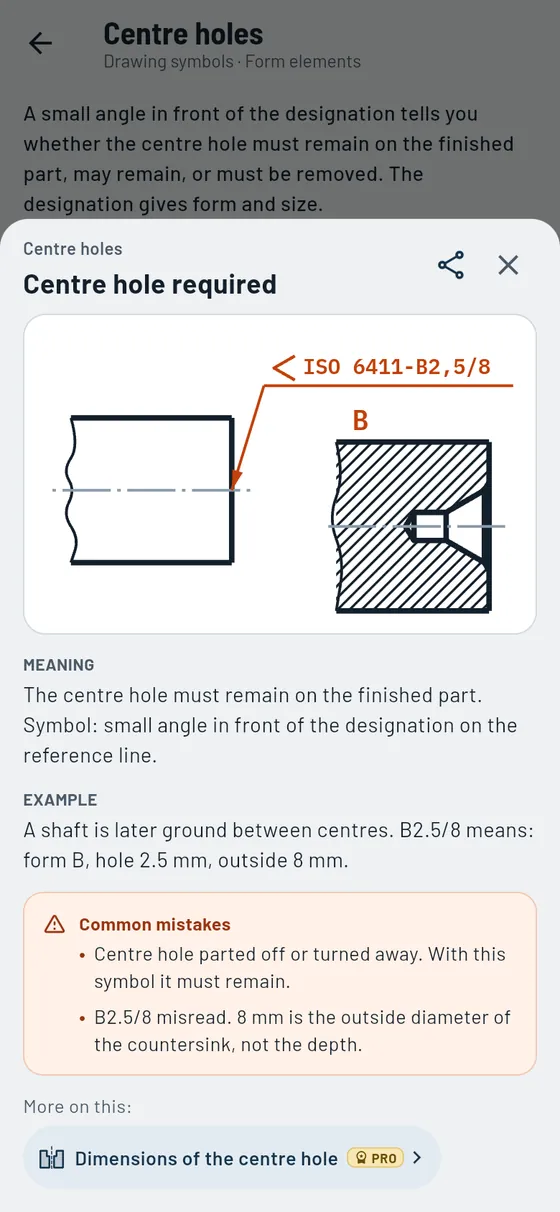
A centre hole is specified on the shaft in the drawing.
Centre hole- Meaning
- must remain on the part
- Example
- Form B, hole 2.5 mm
